Welcome to IntelliSense: Your Destination for Cutting-Edge Design Tools
At IntelliSense, we're dedicated to providing top-of-the-line design tools to fuel innovation and streamline your workflow. Welcome to our platform, where creativity meets efficiency in design.
Our design software sets the standard for excellence, offering a comprehensive suite of tools to meet the diverse needs of designers across industries. From conceptualization to implementation, our intuitive platform empowers users to bring their ideas to life with precision and ease.
With IntelliSense design software, you gain access to advanced features that enhance productivity and creativity. Whether you're designing complex structures or intricate components, our tools are equipped to handle the most demanding design challenges with ease.
Ready to take your designs to the next level? Explore the possibilities with IntelliSense and experience the future of design today.
We certainly were.
When you think about it, MEMS layout is one of the most cumbersome parts of the design process, involving countless revisions, incompatible data formats and minute details. The challenges of MEMS layout are compounded further by the fact that most tools available are IC layout tools, or less-appropriately, architectural design tools.

Blueprint is the first layout tool designed specifically for the MEMS community. Our goal with Blueprint was to revisit the workflow of the layout engineer and create a tool that would be effortless to learn and use.
Our design philosophy for Blueprint is: "simple things should be simple, complex things should be possible." That‘s why our product provides configurable palettes that you can drag and customize to your needs; clearly illustrated icons; and configurable grids and guides - all of which make device layout easier than ever.
We even went a few steps further... automatically linking masks created in Blueprint to process steps for creating 3D visualization of your device. What’s more, Blueprint users can now link the layout with automatic mesh creation and refinement for device-level analysis!
Full custom layout requires your undivided attention on the job at hand. That is why we designed Blueprint with a minimalist sensitivity that maximizes the drawing area. Cells, layers, grids are all available at your fingertips, but take up very little real estate, panels neatly hide after you have used them, toolbars can be torn-off and repositioned to you liking and then closed when you don't need them. All-in-all, providing a very zen experience so that you can draw and edit away without distractions!

Current layout tools treat you like a parking attendant at a crowded lot. Constantly shuffling between views and managing a lot of administrative trivia like layer visibilities, grid sizes, snaps, cells and views. Blueprint introduces a simple solution - Bookmarks. A Bookmark can contain layer states, grid preferences, viewports, view states, grid information, snap settings, transparency settings, and cell states.
Add a bookmark and your current settings are saved. You can then switch to other parts of the drawing. Switch back to a bookmark, and you are back to the drawing, exactly as you left it before.

If you've ever used AutoCAD, then Blueprint will seem very familiar to you. Run commands from the command line or use the customizable keyboard shortcuts for quick and easy drawing. Enjoy a familiar interface coupled with the immense capability of a layout editor specialized for MEMS design.
Blueprint makes it easy for you to tailor the interface to your liking. Customize keyboard shortcuts and manipulate toolbars and snap settings to match your drawing style. Modify performance parameters to adjust redraw speed and level of visible detail. When you're finished, save the information to a user profile, so you can easily load your customized settings later.

No other layout tool is so optimized for MEMS design as Blueprint. Advanced drawing tools like Béziers, splines, and poly-lines are a breeze to use, and multilingual text is fully supported.
Use the Pathfinder operations (add, intersect, subtract, divide, NOR, XOR, grow, shrink, make ring, extract ground plane) to quickly create complex shapes. Modify, align, or distribute shapes easily using the keyboard or the mouse.

The possibilities are endless when it comes to Blueprints snap settings. Snap to common features like endpoint, midpoint, center-point, or intersection points or more advanced features such as tangential or perpendicular points. You can even snap to polar angles and distances in the absolute frame or relative to other objects. The toolbar is fully customizable, so you can select any combination of snaps to be active at a given time.


With Blueprints measurement functions, you can easily measure linear distances, perimeters around a specific shape, or areas of selected objects. Easily add dimensions to your drawing and customize them to the style of your choice.
If you're working with cells and arrays, then Blueprint is the tool for you. Blueprints Cell Manager makes it easy to keep track of cells and manage their hierarchy. You can easily edit and insert cells and arrays and scale or rotate them to your liking.
Ever had troubled visualizing what your mask looks like in 3D? Blueprint solves that problem! Just select a process flow to reference, draw a line across any part of your mask, and instantly see the cross-section of the device along that line. Not only can you see the final cross-section, but you can jump to any step of the process flow to see the cross-section at that step.
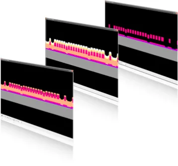
Anyone who has ever tried to hand-draw a process flow in PowerPoint knows how time-consuming it can be. Thankfully, Blueprint can create one for you with the click of a button. The PowerPoint file contains the cross-section and process parameters of every process step, as well as handy summary slides for easy reference. Sharing process information across your organization has never been easier.
Download sample PPT/PDF files:
3 level Poly Process (Cross-Section)
Electrothermal Actuator (3D)

2D cross-sections are great, but sometimes you might want to see your full model in 3D. Blueprint makes this easy with automatic export to FabViewer, the process visualization tool in IntelliSuite. Here you can fully inspect your 3D model and export PowerPoint, image, or video files.

TapeOut is an all-angle Design Rule Check (DRC) engine designed specifically for MEMS. With TapeOut, you can work with convex polygons, Béziers, splines, or other complex MEMS shapes knowing that you've got a robust DRC engine behind you!
Design rules are easy to set up using the TapeOut Deck editor featuring the familiar, friendly IntelliSuite interface. You can sort, group or turn on and off rule checks with the click of a button. DRC can be run on the entire drawing or just portions of the drawings such as selected polygons or blocks.


(a) TapeOut features a familiar and easy to use deck editor (b) An easy-to-use error navigator allows you to breeze through errors (c) intuitive error markings allow you to quickly identify and fix the error at hand.
An intuitive error navigator within Blueprint allows you to easily identify and fix errors. Error markings show you the angles, dimensions or distances causing the errors so that you can intuitively understand and fix the errors. Errors can be sorted by design rule or by blocks, allowing you to breeze through large drawings. Within minutes, your layouts will be error-free and ready for the cleanroom!
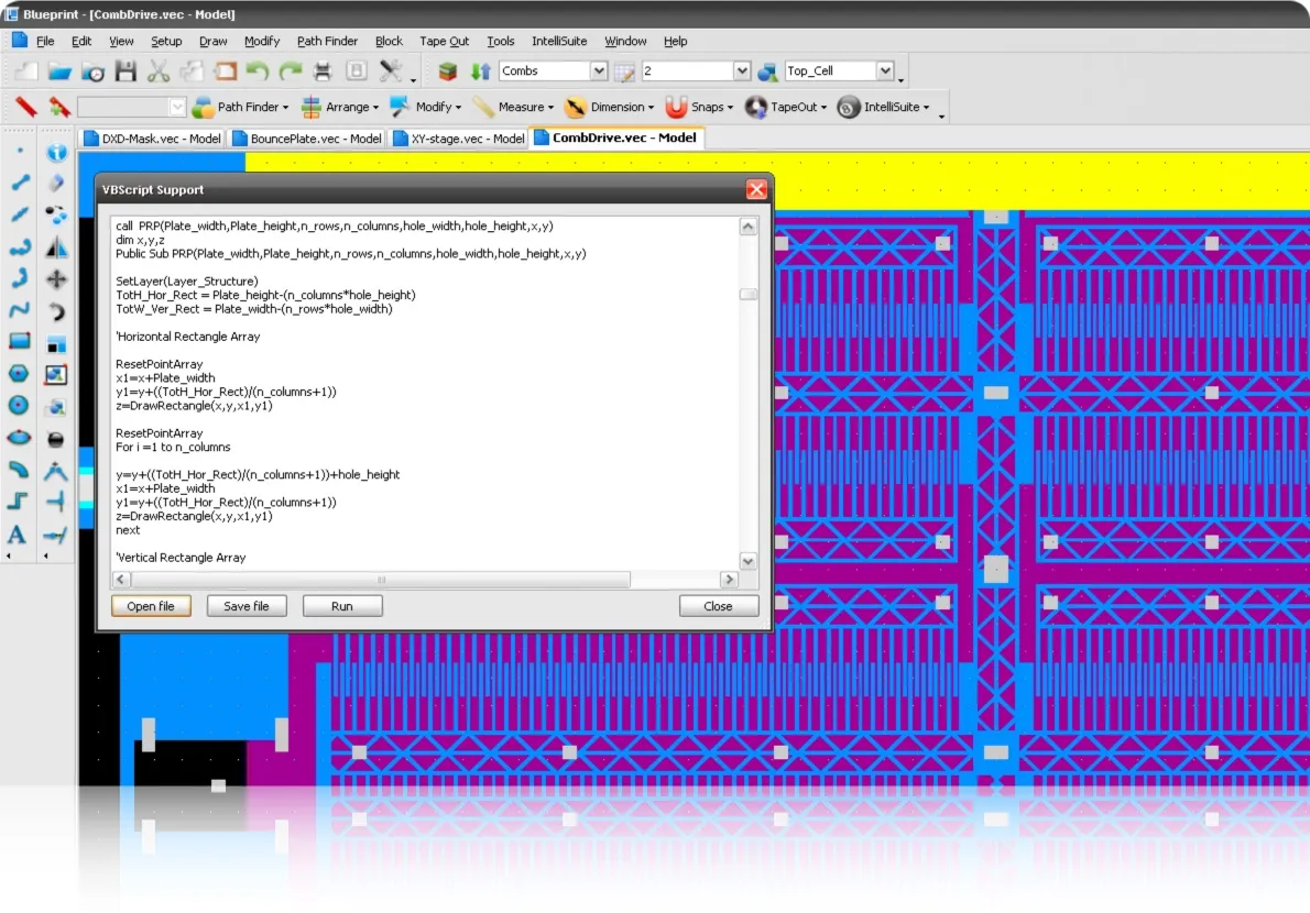

Blueprint is fully scriptable, enabling you to create complex parametric cells and drawings through scripting. Blueprint allows full support for Windows Script Host (WSH) which allows language independence for scripting. You can use built in VBScript based scripting or use any language of your choice (Jscript, Python, Perl, Tcl/Tk) by installing the appropriate language support. Or, choose from our large library of scripts that can be modified to suit your needs.

Working together, IntelliSuite and SYNPLE give test engineers a straightforward method for creating parametric test structures and design of experiments (DoE) during the layout process. What's more, our analysis and system simulation tools allow you to perform a vast subset of MIL-STD (750/883), JEDEC (JESD22) and Telcordia (Belcore) tests in software before the actual fabrication. For success in your next test, turn to IntelliSuite!

TapeOut is an all-angle Design Rule Check (DRC) engine designed specifically for MEMS. With TapeOut, you can work with convex polygons, Béziers, splines, or other complex MEMS shapes knowing that you've got a robust DRC engine behind you!
Design rules are easy to set up using the TapeOut Deck editor featuring the familiar, friendly IntelliSuite interface. You can sort, group or turn on and off rule checks with the click of a button. DRC can be run on the entire drawing or just portions of the drawings such as selected polygons or blocks.


(a) TapeOut features a familiar and easy to use deck editor (b) An easy-to-use error navigator allows you to breeze through errors (c) intuitive error markings allow you to quickly identify and fix the error at hand.
An intuitive error navigator within Blueprint allows you to easily identify and fix errors. Error markings show you the angles, dimensions or distances causing the errors so that you can intuitively understand and fix the errors. Errors can be sorted by design rule or by blocks, allowing you to breeze through large drawings. Within minutes, your layouts will be error-free and ready for the cleanroom!
3D Builder gives you as much control over the device meshing process as you need. On one hand, automatic meshing tools can generate near-optimal meshes, while on the other, interactive tools allow you to further refine the meshes to your hearts content. Think of it as the Tiptronic™ of meshing tools — enabling you to switch from automatic to manual gears. Thanks to our strong attention to real-world usage patterns and ease of learning, you will be able to spend more time on the design and less time poring through manuals.


3D Builders auto-meshing engine can create a meshed 3D structure from a set of masks at the touch of a button. Multi-layer connectivity and non-manhattan geometries are no longer a problem - even the most complex geometries will be meshed in seconds. The self-adapting meshing feature will create small elements where you need them and large ones where you don't - ensuring the most accurate results with the fastest possible compute time.

View 3DBuilder automeshing in action
Download 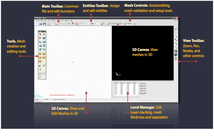
3D Builder also gives you unparalleled control over the mesh creation and refinement process. You can easily import structured and unstructured grids in a variety of formats (ANSYS, ABAQUS, PATRAN neutral file, IntelliSuite) or start with a blank slate for creating meshed 3D structures manually. Regions can be sliced (subdivided) using a number of algorithms, and popular refinement techniques - like spider-web meshes, corner frame meshes or zippered slicing - can be applied with a simple click of the mouse.
3 level Poly Process (Cross-Section)
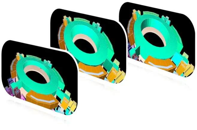

3D builder allows you to create parametric meshes that can morph across design parameters such as film thickness, air gaps, sidewall angle and skew, line width offsets without need for remeshing. Meshes can grow or shrink in feature sizes, expand or contract in thicknesses, sidewall angles, skews can be changed with the touch of button, all without constant and time-consuming remeshing.
Use morphing techniques to grow or shrink, taper, twist or shear meshes
 AutoMeshing Bullet-proof Manhattan, isotropic and adaptive meshing algorithms
 Parametric meshing Quickly vary important device parameters such as thicknesses, gaps or sidewall angles without needing to re-mesh
 Mesh Healing Validate meshes and automatically heal meshes
 Template based meshing Automate mesh creation based on process or geometric templates
 Conformal or planarized meshing Support for conformal deposition and surface planarization
 Powerful geometry creation and editing Powerful tools to create and edit polar or rectilinear meshes
 Mesh morphing Use morphing techniques to grow/shrink, taper, twist or shear meshes
 Mesh Refinement Refine meshes by slicing, zippering, spider-webbing or framing
 Defeaturing & Simplification Exclude unnecessary details (dimples, for instance) and simplify polygons before meshing
 Powerful export capabilities Export to IntelliSuite Multiphysics, ANSYS, ABAQUS, PATRAN, SIMULIA and I-DEAS
Hexpresso is a mesh synthesis tool that allows you to generate high quality all hexahedral meshes from schematics, layouts or process flows. Enjoy Hexpresso for MEMS, Microelectronics, PCB and packaging applications!

Hexpresso brings you a blend of robust meshing combined with state-of-the-art mesh algorithms to automatically produce all hexahedral meshes in a jiffy. A powerful, yet easy to use interface allows you to tailor meshes to suit your modeling needs.

Design analysts spend a significant amount of time manipulating design geometries and meshing structures. Most MEMS design tools require manually partitioning 3D geometry into mesh-able regions. Studies have shown that in a typical 10-step design through analysis cycle, a staggering 73% of time is spent in geometry manipulation and meshing
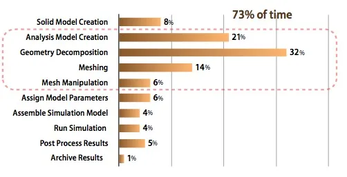
Design through analysis man-hours spent (not CPU hours). A typical 10-step design through analysis cycle (excluding iterations) is shown. A staggering 73% of time is spent in geometry manipulation for meshing. [Courtesy: Matt Staten, Computing and Modeling Dept, Sandia National Labs]
While many tools provide automated tetrahedral(tet) meshes they are suboptimal for MEMS design. In the words of a Sandia Labs design analyst, “The only people who use tets are those who don’t care about their answers”.
Hexahedral meshes are ideal for MEMS. However, automatic generation of hex meshes for complex MEMS structures has been a big challenge … until now
 AutoMeshing Hexpresso takes you from process flow, schematic or layout to hex mesh in one click!
 Mesh Morphing morphs the mesh to make quick changes, without having to remesh
 Defeature Exclude unnecessary details (dimples, for instance) and simplify polygons before meshing
 Mesh Refinement Specify areas of mesh refinement. Or in case of schematic driven meshing allow Hexpresso to automatically identify areas of high stress.
 Autodetect High stress regions such as springs, beam joints, plate joints are automatically identified and refined (in schematic based meshing)
 Parametric Mesh Quickly vary important device parameters such as thicknesses, gaps or sidewall angles after meshing (3D Builder required)
 Transform Perform mask transformations on the fly. Translate, offset, or rotate mask information.
 Tightly integrated Tightly integrated within Blueprint, IntelliFAB, and SYNPLE, Hexpresso allows FEA novices and beginners to generate high quality meshes for 3D analysis