

Welcome to IntelliSense's System Modeling page, where cutting-edge technology meets versatile solutions for your modeling needs. Our comprehensive suite of system modeling tools empowers engineers and scientists to simulate and analyze complex systems across various industries.
At IntelliSense, we understand the importance of accurate and efficient modeling. That's why our system modeling solutions are meticulously crafted to offer unparalleled performance and flexibility. Whether you're working in aerospace, automotive, energy, or beyond, our tools provide the capabilities you need to drive innovation and optimize your designs.
Our intuitive interfaces and advanced algorithms make it easy to create, simulate, and refine your models with precision. From dynamic system simulation to control system design and optimization, our tools deliver actionable insights that drive informed decision-making and accelerate product development cycles.
Experience the power of system modeling with IntelliSense. Explore our suite of tools today and discover how you can streamline your modeling workflows, unlock new insights, and stay ahead of the competition. Revolutionize your approach to system design and analysis with IntelliSense's cutting-edge solutions.
Developed by IntelliSense to answer the unique needs of the microsystem and nanosystem community, SYNPLE is a system-level simulator for multiscale (macro, micro, nano) phenomenon simulations. As a MEMS design professional, you always seek new ways to realize your designs and, ultimately, bring them to market. With SYNPLE, you can. This revolutionary tool will enable you to work in multiple domains - simply and without limits.

Do your current simulation tools stifle the reach of your imagination? Impose limitations on your designs and work product? SYNPLE will allow you to follow your out-of-the-box vision - and create simulations to match. SYNPLEs advanced element libraries, user-defined elements and a user-expandable architecture will significantly increase your present multi-physical simulation capabilities. As a result, you can explore a whole new design universe and be as creative as you want to be!
When IntelliSense developed the SYNPLE system-level simulator, we incorporated user benefits that would make a real difference to your bottom line, rather than adding lots of extraneous bells and whistles. First and foremost, SYNPLE enables you to explore a large design space in a short amount of time - which maximizes your time and creativity. To save time further, it allows you to funnel, and quickly whittle down, a large number of design options.
And to minimize your manufacturing costs, SYNPLE makes it possible to understand the ultimate impact of your design parameters on manufacturing yield. Enjoy maximum creativity at minimum time and cost - it's that SYNPLE!
While SYNPLE's range is wide enough to create complex simulations, its user interface is exactly what the name implies - simple! In fact, if you've ever created a flow chart (who hasn't in this business?), then you'll take to SYNPLE like a fish to water. By relying extensively on the familiar "drag-and-drop" function, rather than arcane interfaces, its both easy to learn and easy to use.
SYNPLE's new auto-wiring feature eliminates the need to manually connect all of your elements. Thermal, electrical, mechanical, piezoresistive, and electronic properties are all connected through one bus-based wire. Not only does this make the schematic much easier to read, it eliminates the tedious task of drawing multiple wires, allowing you to focus on what's really important - designing!

SYNPLE's auto-wiring feature makes it easy to build up a complex device in minutes. Thermal, electrostatic, mechanical, piezo, and electronic properties are all connected through one bus-based wire. Friendly manager windows make it easy to define your ambient fluid parameters, material properties, and element parameters. Just input the data once, and it will be automatically saved and inserted into the relevant calculations.
To further your capabilities, IntelliSense ships SYNPLE with an extensive line of comprehensive element libraries for your use. These include analog, digital, mixed-signal, micromechanics, semiconductor, MEMS and biological libraries. You can even use advanced elements such as multi-layer, CMOS, or piezoelectric beams. Whether it be radial comb drives or common MEMS spring designs, we have taken into account everything that a MEMS designer would need.

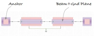
SYNPLEs top down modeling capability enables you to drag and drop individual elements from different domains and wire them up to create complex systems. For instance, you might use elements from SYNPLEs MEMS library - which includes atomic elements like beams and plates, compound elements like serpentine springs and comb drives, and device elements like switches, accelerometers and gyros - to create your own complex systems from the bottom up.
Is bottom-down modeling a more desirable capability for your needs? If so, then SYNPLE makes that simple as well - allowing you to import your existing finite element models and combine them into new, more complex systems.


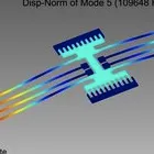
IntelliSuite extracted system models are full 3D models. Hence, Synple can provide full 3D output of the system response. As a result the response of a device to a complex mechanical or electrical input can be captured accurately. (a) Extracted beam model responding to a 50 kHz voltage input, note the initial deformation in the beam shape due to residual stress effects (b) the same beam responding to a 3 MHz voltage input (c) a micro-mirror response showing multiple modes being actuated.
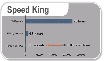
The seamless integration of System Model Extractor (SME) with SYNPLE is a powerful combination that allows you to create accurate N-DOF (n degrees of freedom) device-level black box models that fully capture the dynamic and harmonic responses of even the most complex of MEMS devices. Our tests have shown a 100-1000x improvement in speed in performing dynamic analyses compared with traditional FEA.
Picture this: you have explored a large design space using a schematic-based tool like SYNPLE, and now your device design is optimized. Time to spend tedious hours drawing your mask layout, right? Wrong! The MEMS Synthesis feature will extract a fab-ready layout from your schematic with one click. This isn't any simplified layout either - you can easily generate real-world details like stress relief curves, etch compensation features, dimples, and bumpers. Making a change to your design? Why spend hours modifying your layout when you can change the device parameters in SYNPLE and generate a new mask set in seconds?


Synple goes from schematic to mask layout, meshed model for full verification or to process flow in one click. (a) Mask synthesis in action (b) Synthesized masks include real world features such as stress relief curves, bumpers, dimples and other esoteric features, saving you time (c)and now synthesis capabilities extend to full Hexahedral mesh generation thanks to the magic of Hexpresso.
As if this wasn't enough, you can use the MEMS Synthesis feature to take your design two steps further! The synthesis routines can convert the schematic to a process flow to be used as a basis for your fabrication. In addition, you can use the Hexpresso meshing engine to automatically convert your schematic to a 3D meshed model ready for multiphysics analysis.

In addition to design exploration, Synple allows you to perform Design for Manufacturability studies such as sensitivities to design parameters, paretos, process corner analyses or full Monte Carlo simulations for yield estimation.
Graphs and charts are great, but haven't you ever wished you could really see what the behavior of your system looks like? Now you can! SYNPLE can directly export the results of your simulation to the 3D post-processing module VisualEase. In VisualEase, you can view full 3D animations of your system simulations.


SYNPLE allows you to visualize your system response in 3D without having to go through tedious FEA modeling. 3d results can be obtained in seconds. 3D animations of classic MEMS systems are shown above. This includes, a Bandpass filter, a mode matched tuning fork gyro and the classic Tang Resonator.
SYNPLE links to the new WaveRunner waveform and data analysis tool. With WaveRunner, you can easily create and export professional-looking plots. WaveRunner comes with a number of plot templates ranging from simple charts to Bode plots to sophisticated trajectory plots and parametric exploration 3D plots so that you can explore your data with ease. Multiple cursors (x and y) are available to measure distances along any dimension. Whether you're creating a multi-curve or Monte Carlo plot (or any plot in between), you won't find a result analysis tool that is more powerful or easier to use.


WaveRunner capabilities extend from simple waveform analysis to sophisticated data analysis. Users can create and explore data in a number of publication ready formats.

Working together, IntelliSuite and SYNPLE give test engineers a straightforward method for creating parametric test structures and design of experiments (DoE) during the layout process. What's more, our analysis and system simulation tools allow you to perform a vast subset of MIL-STD (750/883), JEDEC (JESD22) and Telcordia (Belcore) tests in software before the actual fabrication. For success in your next test, turn to IntelliSuite!
Picture this: you have explored a large design space using a schematic-based tool like SYNPLE, and now your device design is optimized. Time to spend tedious hours drawing your mask layout, right? Wrong! The MEMS Synthesis feature will extract a fab-ready layout from your schematic with one click. This is not any simplified layout either - you can easily generate real-world details like stress relief curves, etch compensation features, dimples, and bumpers. Making a change to your design? Why spend hours modifying your layout when you can change the device parameters in SYNPLE and generate a new mask set in seconds?


Synple goes from schematic to mask layout, meshed model for full verification or to process flow in one click. (a) Mask synthesis in action (b) Synthesized masks include real world features such as stress relief curves, bumpers, dimples and other esoteric features, saving you time (c)and now synthesis capabilities extend to full Hexahedral mesh generation thanks to the magic of Hexpresso.
As if this wasn't enough, you can use the MEMS Synthesis feature to take your design two steps further! The synthesis routines can convert the schematic to a process flow to be used as a basis for your fabrication. In addition, you can use the Hexpresso meshing engine to automatically convert your schematic to a 3D meshed model ready for multiphysics analysis.
IntelliSense introduces a new class of extraction tools for dramatically reducing the computational time to perform accurate analysis of MEMS. Based upon cutting edge, Krylov subspace model reduction algorithms, very large nonlinear thermoelectromechanical FEM models can be reduced into computationally efficient behavioral models. These behavioral models can be used in system simulators and analog mixed-signal workflows.

IntelliSuite behavioral models fully capture the complex nonlinear dynamics inherent in MEMS due to electrostatic forces, residual stresses, squeeze film damping, packaging effects and multiple mechanical degrees of freedom. These models fully capture all the harmonic modes of the MEMS so that you can fully account for sub-harmonic contributions while developing readout or control electronics.


IntelliSuite extracted system models are full 3D models. As a result system simulators can provide full 3D output of the system response. As a result the response of a device to a complex mechanical or electrical input can be captured accurately. (a) Extracted beam model responding to a 50 kHz voltage input (b) the same beam responding to a 3 MHz voltage input (c) a micro-mirror response showing multiple modes being actuated.
Extracted models match FE simulations in accuracy but are 100-1000 times faster than traditional FE based simulations.
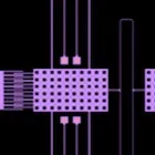
Coupled Fluidic, Electrostatic, Mechanical analysis of a 3x3 micromirror array; effect of one mirror being actuated on surrounding mirrors. Extraction techniques can speed up computation by a few orders of magnitude.

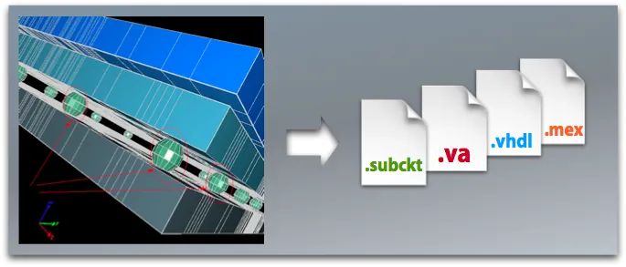
Extraction is performed in 3 stages. (a) The total strain and capacitance energy and fluid dissipation is captured (b) a Lagrangian Look Up Table (LUT) formulation is used to generate a description of the device and (c) the model is output into various HDLs for incorporation into EDA tools of your choice.
System model extraction is based upon capturing the total energy within a MEMS device. Strain energy, electrostatic energy, fluidic dissipation and other damping terms are captured for each mode of interest. Sub-modeling techniques can be used to capture the interaction of the packaging related stresses on the device as well. Process related aspects such as residual stresses and strain gradients in films, orthotropic or anisotropic material properties, electrostatic levitation effects, thermal or packaging effects are fully captured in the resulting model. The extracted model is an arbitrary N-DOF 3D Model. User can use the 3D model to investigate dynamics of the MEMS device either locally or in full 3D .
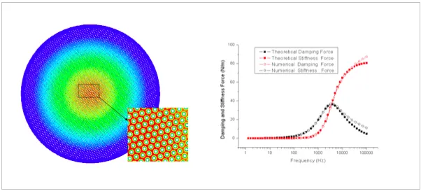
Packaging analysis can now capture fluidic damping and spring force for complex MEMS structures. Our macromodel techniques now extend to fully capture fludic dissipation and automatically include ambient damping into system simulations. Fluidic damping can be captured for each of the modes of interest.
As MEMS make their successful entry into mobile devices, the demand for slim profile packages becomes paramount. MEMS devices have started to leverage IC stacking technologies such as wafer bumping, die-on-wafer assembly, through-silicon vias (TSV) and towards low-cost Wafer Level Chip Scale Packages (WLCSP). As the MEMS subsumes the package into the structure, the need for efficient package modeling and compensation of packaging effects at the die level become important.
One of the most innovative features is the ability to include packaging effects on the device performance into the system models. Package extraction and sub-modeling techniques allow you to estimate the impact of the package stresses and temperature effects on the system performance.
Models based on rigid body approximations. These capture up to 6 mechanical DOFs and multiple electrical DOFs. Useful for designing readout electronics
Accurately capture second order effects such as parasitics, non-linear deformation, temperature effects and package related effects. Useful for designing compensation electronics
Fully capture harmonic and sub-harmonic response of the devices. Useful for designing active controls of MEMS.
Model output to SYNPLE, Verilog-A, VHDL, PSPICE, HSPICE, Simulink (with purchase of EDA Linker)
EDA Linker allows you to co-simulate your micro-devices along with the electronics in your favorite mixed signal or system level environment.
EDA Linker allows you to incorporate IntelliSuite directly into your EDA workflow. Whether you are using a Cadence, Mentor, Synopsys or Tanner environment, or a mixed tool environment IntelliSuite will fit right in.
EDA Linker allows you to easily create component models (in VHDL, Simulink, SPICE etc.) of any complex mechanical or electromechanical structure. These are not simplistic 6-DOF reduced models but a full 3D (N-DOF) representation of the structure.
With EDA Linker derived models you to perform a comprehensive sealection of analyses on your MEMS devices - from DC, AC, transient, steady-state, analyses.
EDA Linker uses the same sophisticated underlying technology as our popular System Model Extraction module. Users can easily convert complex electro-mechanical devices such as gyroscopes, resonators, sawitches etc. into an equivalent hardware description language with the click of a button.
EDA Linker now allows you convert output from the Electromagnetic into Touchstone, SPICE or Pole-Zero Residual format.
By creating or importing a mask file, users can:
LOCATION
 220 Broadway, Suite 102, Lynnfield, MA 01940, USA
 sales@intellisense.com
 +1781.933.8098
fff
india@intellisense.com +91 98866 35654© IntelliSense. All rights reserved.

 MEMS Extraction and Verification